To detect the white object on the dark wall, we chose to use combined light sensors. Each of these sensors needs their own little PCB to reform the incoming voltage and to be able to communicate with the microprocessor.
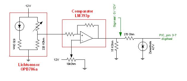
We chose a combined light sensor, the OPB706a. This sensor contains a transmitter as well as a receiver. The transmitter transmits infrared light that will be scattered (especially by white objects) and therefore can be picked up be the receiver again. This system allows Vertigo to detect weither or not there is an object in front of him. We push this signal through a comparator (LM 393), which digitalizes it, sending a high signal to the microprocessor when an object is detected, a low signal when no obstructions are in sight. The potentiometer will allow us to govern the sensitivity of the sensor to reduce the impact of the surrounding light.
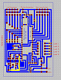
This part of the circuit is preferably designed as a small separate pcb which will contain the sensor. There are two main reasons: The output signal from the sensor gets partly processed and enhanced, very close to the sensor. This reduces the influence of noise on the signal. Besides this, a separate pcb for every sensor ensures you a smaller main pcb, what will make your life easier when designing the layout of your board.
A second part of the light sensors circuit will be mounted on the main board. The small board will send a digital signal to the main board. This signal will consist of either 0V or 12V. The microprocessor however, can only handle voltages up to 5V, so downgrading the voltage will be necessary. This can be done by connecting the signal line with ground by a zener diode of 4,7V. This diode will switch when the voltage is high (12V) and force its own voltage (4,7V) onto the signal line. To limit the current running to ground, a resistor (here: 270 Ohm) is placed before the diode. Make sure not to use a resistor that is too large, as this may pull down the voltage over the zener diode.