The governing of the electric engines is one of the most complicated parts of the electronic design, since both the engines must be governed separately and must be allowed to run forwards as well as backwards. This means reversing the voltage, which is not always an easy thing to do. Luckily, someone did most of the work for us by designing a 'Motor Driver Chip'. Of course you can also design your own circuit; we will get back to you on this option in a second.
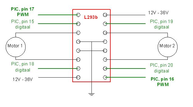
The 'Motor Driver chip L293b' is a 16 pins chip that can govern to little electric engines. The circuit is simple and the software required is fairly easy to write. The PIC has two PWM output ports, which we will use to send signals to the motor driver chip. This PWM signal will govern the voltage level of the engines by turning the chip on and off at a fairly fast rate, depending on the required voltage. On top of the two PWM pins, we will also use two digital signals for every engine. Depending on the combination of these output signals, the engine will turn left, right or stand still.
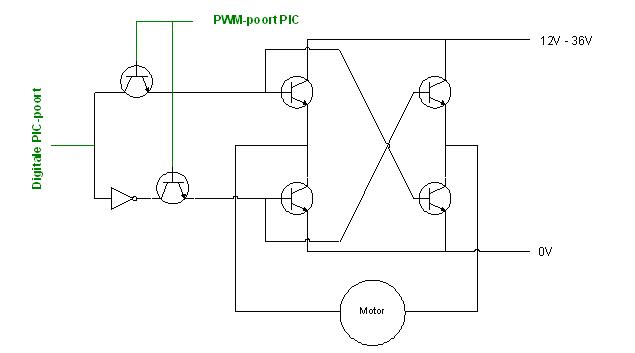
If you don't have a 'Motor Driver chip' at your disposal, you can always govern the engines by a transistor circuit. The scheme bellow shows the circuit for one engine. The digital port will manage the direction of the turning of the engine, the PWM port governs the voltage supplied to the engine and therefore the power of the engine. This circuit will require a larger pcb and a higher number of components, which will make the whole board more complex to design. The advantage of this option however, is the fact that lesser PIC pins are used, and so there is more room for extra sensors.