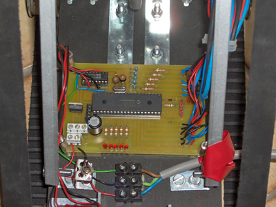
The design of the printed circuit board is the final step in the electronic design of your robot. All the previous steps hand you the tools and circuit you need to design the layout of your pcb. To allow yourself to debug easier, you might want to add some leds to your design. These leds don't have a vital function, but are very handy when you want to debug or run some test programs to check your electronics etc. We added five leds and that did the trick for us. Now you really know everything to design your own printed circuit board, but we still made it a little easier for you. Below you see a possible pcb design you can use for Vertigo:
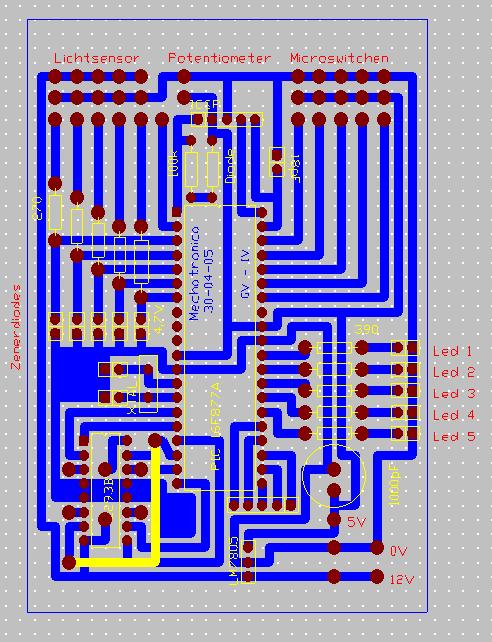
This design uses the 'Motor Driver chip', supplied by a 12V power line. Depending on the engine, the weight of your robot and the force of your magnets, your engines might need more power, so a higher voltage. If this is the case, you can slightly adjust the layout above to be able to supply 36V to the 'Motor Driver chip'. The pcb for the light sensors might look like this:
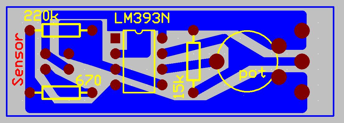
The comparator chip contains 2 comparators. To avoid noise generated by the comparator that we don't use, we connect every pin of the chip. This avoids floating of non connected pins. This concludes the electronic design. We have defined all components and their circuit, explained their function and designed the printed circuit board. Now there is only one more thing left to do: Solder and cable the whole thing. This will keep you buy for several long nights. Enjoy