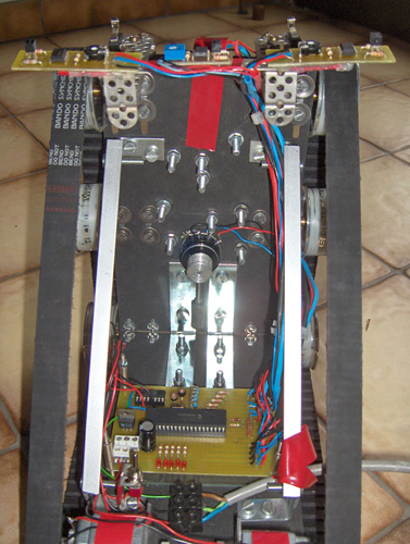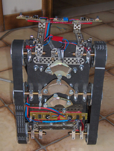
Although the electronic design is discussed rigorously in the next section, we'll already give you a small overview here. After all, the electronics have to be integrated in the mechanical design. To position the different sensors, we mainly used meccano, since this is light and gives you many possible attachment points. To attach the sensors to the meccano we used either screws and bolts, or thermal glue. The different electronic parts are: the light sensor, the micro switches, the potentiometer and the printed circuit board.
The potentiometer The potentiometer is used to identify the robot's position on the vertical plane. The potentiometer must be flexible and light. With the help of a small weight and gravity, the potentiometer changes position as Vertigo changes orientation. So we can identify the robots position according to the voltage delivered to the processor. The potentiometer is mounted somewhere on the vertical plane.
The light sensors The light sensors are used to detect the white objects without contact, scattered on the vertical plane. You need five of these sensors. Two are used when Vertigo is on the ground, trying to find the black wall, the other three are used when climbing the wall. You can find some more information in the electronics and the software section.
The micro switches You'll also need five of micro switches. Three are mounted on the contact area with the vertical wall. They detect whether the robot is positioned on the vertical plane or not. The other two are positioned on the front of Vertigo, to detect the small beam at the top of the vertical wall.
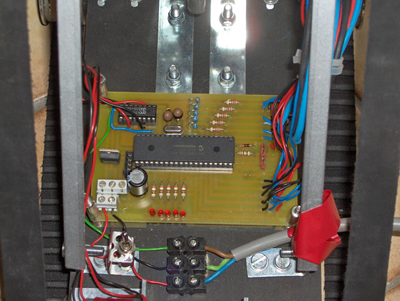
The printed circuit board This is the central circuit board of Vertigo. It contains most of the circuits needed and the microprocessor, the brains of Vertigo. All the sensor output signals end up here and get processed by the microchip. Of course, this microchip needs to be programmed first. You can find the software needed, as well as some information in the software section.